Capstone Humanoid Joint Mechansim

Problem Definition

  • To design and build a spherical parallel manipulator mechanism for humanoid joint applications
  • The project idea was given to me by the director of robohub at UW. 
  • Main design targeted the shoulder because this was the most demanding joint for this application. I wanted a challenge. 

 Typical Humanoid Shoulder Joint Designs

Humanoid shoulder joint design aims to model a ball-in-socket joint with 3 rotational degrees of freedom. (F) Flexion, (A) Abduction, and (R) rotation

They do this by having a serial stack of actuators perpendicular to each other. Most companies use the F-A-R configuration

Red: Horizontal actuator to control flexion on the red axis

It is carrying a motor which is perpendicular to the axis of the red motor. 

Green: This controls the abduction of the arm

Blue: Another motor is carried, which rotates the arm. 

This is how they get their 3 degrees of freedom. 

Why do all companies use this design? 

  • Proven pattern & software fit. Modern humanoid stacks (Pinocchio/RBDL, ROS control, simulators) assume serial trees; ball joints are implemented as 3 revolutes. This makes modeling, whole-body control, estimation, and sim2real much simpler.
  • Manufacturability & service. Fewer precision parts, easy to seal/grease, predictable wear
  • Workspace first. Humanoids need big, human-like ROM for gestures, reach, and manipulation; serial geometry makes it easier to hit those corners without running into parallel singularity walls.
  • Maturity of parallel shoulders for humanoids is low. Surveys show parallel joints for humanoid upper-body use are mostly at prototype TRLs; production deployments are rare.

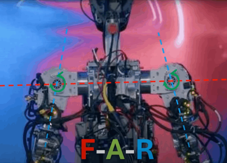
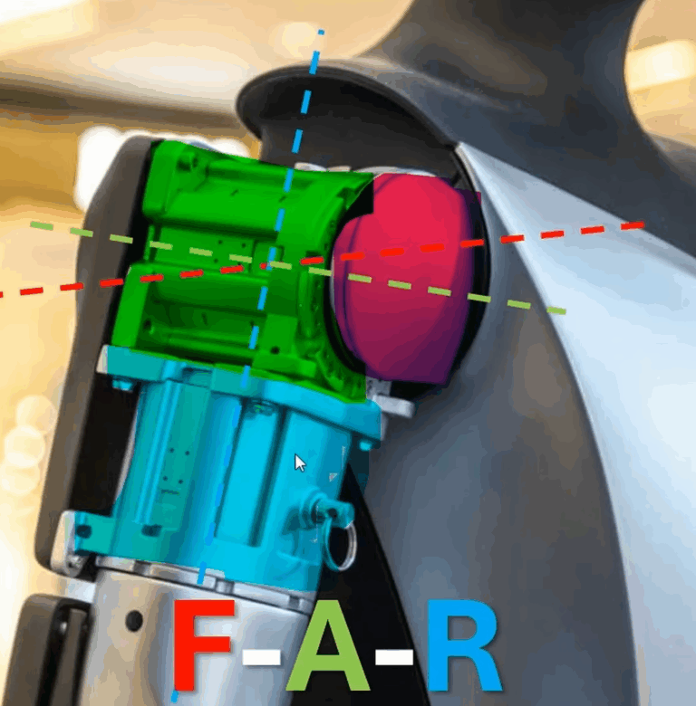
What are the disadvantages of F-A-R designs? 

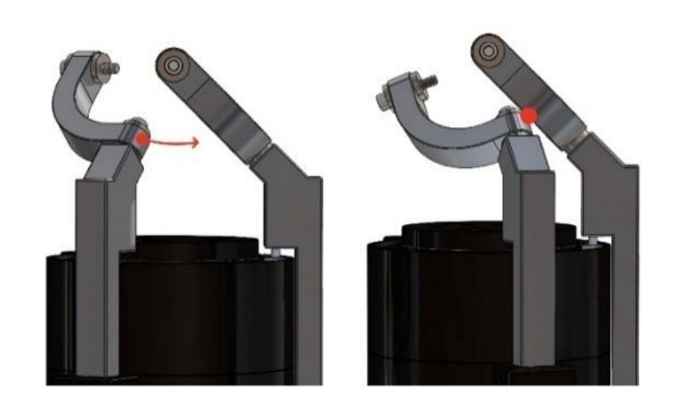
1. When the middle axis approaches 90°, the first and third axes align. That means at 90 degree abduction, you can get ill-conditioned jacobians, huge joint velocities, or abrupt flip in command angles. No controller can remove a mechanism singularity—it can only steer around it

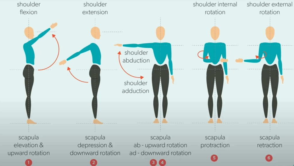
2. Abduction is the worst gravity lever for a robot arm: the proximal F/A actuators must hold the whole arm+payload at long moment arms. Humans offload this using scapular upward rotation and clavicular elevation; without those DOFs, robots either eliminate overhead payloads or run hot keeping the arm out to the side/overhead.

3. The 3rd motor pushes mass distal, raising arm inertia, which requires higher motor currents or gearboxes. A big disadvantage of abduction because motor size is a restriction, and it must carry the weight of the 3rd motor.

Why does nobody use SPMs? 

1. Nasty Singularities 

  • Parallel wrists don’t just have a single, well-placed “gimbal” issue — they have Type-II (parallel) singularities on curves/surfaces inside the usable workspace. Near these, orientation accuracy collapses and required actuator forces/velocities spike

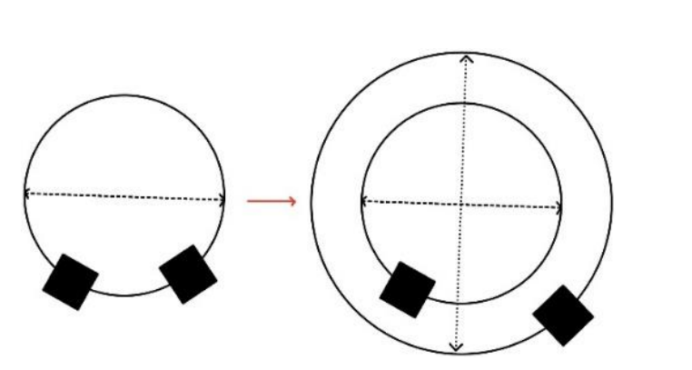
2. Smaller Workspaces

  • A poor fit for a humanoid shoulder that needs big, human-like ROM for gestures, cross-body reach, and overhead tasks.

3. Control is more complex

  • SPMs are closed-loop systems with nonlinear kinematics and multi-solution forward kinematics. That’s more controller logic and trickier safety margins than a simple 3-R shoulder

4. Stiffness in Arms can be weak depending on the design

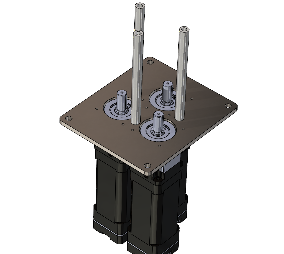
What are the advantages of SPMs? 

1. Low Moving Inertia

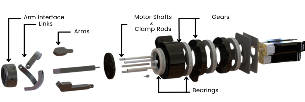
SPMs place actuators and encoders on the torso/base, leaving only short links and passive joints on the moving platform.

Lighter proximal mass = faster, lower-energy swings; less heating at the shoulder
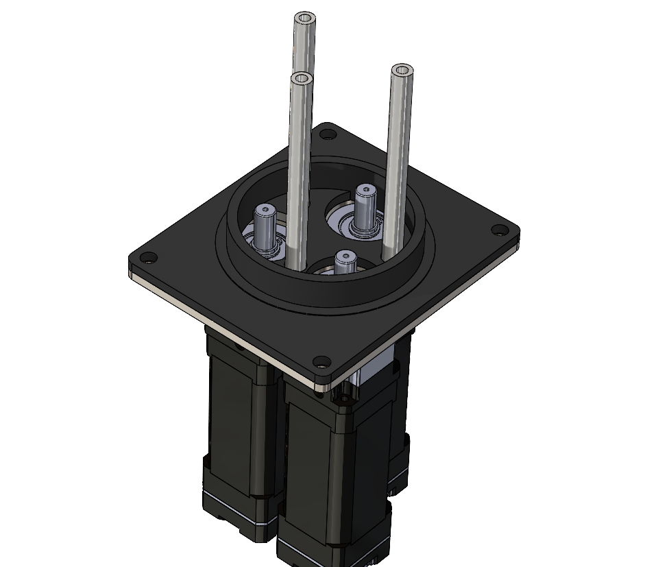
2. High Speed

SPMs are very fast, and have precise pointing under load. 

Low inertia arm, combination of 3 motor torques.

Higher structural stiffness allows for higher control gains, and reduced settling time. 

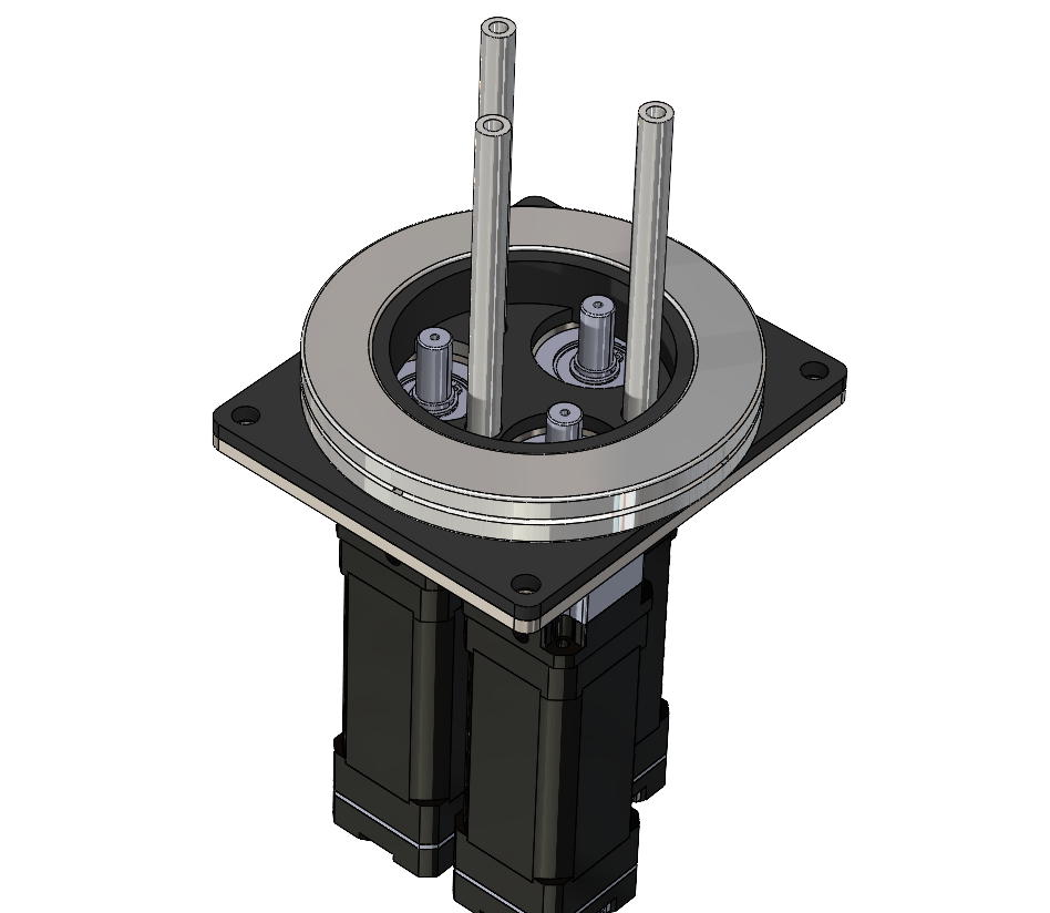
3. Cleaner wiring and sensing

With sensors/encoders fixed on the base (common in SPM wrists), you avoid moving-cable stiffness and fatigue, and you simplify maintenance. It’s a small but real quality-of-life win in production robots.

Goals:

1. Improve the range of motion (workspace) of SPMs in comparison to the normal SPM designs to have a ROM as close to a F-A-R configuration.

2. Improve the load bearing design of the SPM to make it extremely strong

3. To further study SPMs as they are an under-researched mechanism. Control algorithms are hard to come by. If this becomes well known in the industry, then further advancements in SPMs can be made. 

4. To build a cool robotics mechanism to further our mechanical, electrical, and software skills. 

Clear Objectives:

1. Lift a minimum of 5Kg with a 0.6m arm at 0.5 rad/s

2. Weights under 10 Kg and fits within a 20 x 20 cm mounting footprint

3. Has the ability to be scaled down for neck and wrist applications

Roles and Responsibilities: 

  • Lead the mechanical and electrical design and assembly of the system
  • I was a sole contributor to the electrical design
  • A major player in the mechanical design. I did the arm and link, end-effector, and humanoid shell design.  
  • Led weekly team meetings, assigned tasks, and led project presentations to the class. I also set up up our symposium booth
  • Purchased materials, sourced motors, and assembled the unit. 

Technical Approach and Design:

Step 1: Motor Selection

The first step in the design process is determining the motor specifications required for the three motors. This is a foundational achievement because the mechanical and electrical design elements rely on this information.

  • The mechanical design relies on the size of the motor because all three motor shafts need to lie within the diameter of the main gears. Different sizes of motors will directly influence the diameter of the main gear.
  • The motor will also influence the structural integrity of the gears, as the output torque may produce a shear force that is too high on the teeth of the gear.

Angular Velocity and Acceleration

  • The torque output of the motor at a specified speed is the main factor in how the motor is selected.
  • I recorded a slow-motion video of my arm raising at a speed that will set the upper limit of the angular velocity and acceleration profiles of the mechanism.

Position and Velocity Profiles from Kinovea 

From the curves, we can see a maximum velocity of 3 rad/s and a max acceleration of 1.5 rad/s^2

Torque and Speed

From a large table in excel, the minimum speed is 28 RPM, and 15 Nm. This sets the requirements of the motor to be minimum 20 RPM with 30 Nm of torque (safety factor of 2 for torque was decided). We opted for a stronger, but slower mechanism. 

Sourcing Motors

Step 2: Mechanical Design

Bearing Selection

The bear was selected based on what we could source for a reasonable price at the size need. Crossed roller bearings were chosen because they can support both the radial and axial loads seen by the system. 

The drawbacks of these bearings is that they are very heavy, which drastically increased the weight of the system ~3 lbs.

Gear Design

Step 1: Selected 20 degree pressure angle, very common for tooth strength, efficiency and manufacturability. It is the modern standard. 

Step 2: Select Module Size (Tooth Size)

  • Each motor with the 50:1 gearbox outputs 12.5 Nm (0.25 Nm x 50)
  • The size ratio of the circle of motor shafts to annular ring pinion gear will produce ~ 3:1 ratio = 37.5 Nm
  • 3D printing restrictions (0.4mm Nozzle) requires at least 0.8mm module for good quality
  • Size constraint of small driving gear: To have the gears be stackable with the available bearing size, the driving gear must be less than 30mm diameter
  • Material: CF Nylon (80 MPa)
  • Safety factor: 1.5

From here we can determine minimum tooth size

Annular Ring Gear Design

To properly mate the internal ring gear with the pinion gear, the pitch diameter is 79mm. 

Number teeth for 1.5 module = 52.67 so this isn’t acceptable. 

Moving the pitch diameter to 81mm and the mounting distance of the pinion gear to 28.5mm fixes this issue so we have 54 teeth.

Gear Reduction

54/16 – 1 = 2.375

Therefore we will get 30 Nm of torque at the output, which results in 200 MPa bending stress – still theoretically too large for 3D printed gears.

Stackable Gear Design

Arm and Link Design

To design the arms, the geometry of the SPM is determined first. To have uniform movement in all directions of the rotation of arms, while preventing locking of the links, existing SPM designs prove that the axes of the arms should meet at the center of the end-effector disk

Below is the general geometry of one of the gear arms designed.

With this geometry in mind, a problem was found that significantly decreases the range of motion. When the arm rotates, it causes an interference with the link in front of it.

This problem is solved by increasing the diameter at which the colliding arm rotates about. Currently they are both rotating about the base at the same diameter.

The resulting change is shown below, which removes the collision, and ultimately increases the range of motion by 15 degrees. 15 degrees is a huge improvement to be able to get the arm closer to a full forward location. It allows for only 15 degrees internal rotation instead of 30 degrees which would restrict the arm going directly outward. Trigonometric calculations were performed to get the new gear arm to properly align to the center of the end effector. 

The axis of the holes at which the links connect to the end-effector disk, need to all meet at the center of the disk for our SPM kinematic algorithm to work.

Here we can see that one link is longer than the other so the holes align 120 degrees apart, and meet at the center of the disk. Below is the final geometry and shows all axes lining up to the center. 

Cam Roller Addition

A cam roller was added to the bottom of the 2 arms which are subjected to a bending moment that has the potential break the arms. A track was added to the top of the base for the cam roller. This design change secures the arm in place from forces in both directions.

Why that thickness and width of arms and links? – FEA 

Step 1: Simplify the geometry

Step 2: Setup Contacts

Step 3: Create the mesh

Step 4: Analysis Settings 

Step 5: Materials 

Step 6: Add the loads and fixed supports

Step 7: Results

Equivalent Von Misses Stress

Note: 6061 AL has yield strength of 240 MPA (2.4e8). Want to analyze any part which surpasses 80 – 120 MPA (safety factor 2 to 3). 

Note: 316 Stainless Steel bolt has yield strength of 450 MPA. Want to analyze if any bolts surpass 225 MPA (safety factor of 2)

Note: Remember each motor can theoretically only output ~ 30 Nm of torque, which translates to ~ 10Kg of payload capacity. If only one motor is being actuated in the movement, a single motor should be able to rotate to pick up the mass (as a safe conservation). Therefore the max load the arm should see is ~100N. 

I need to do further investigation where the stress above 80 MPA is occuring

Von Misses – Isolating for Links

We can see that the maximum stress in any of the links is 75 MPA, which confirms that each link has a safety factor of 3. This is what we want and designed for in the initial FEA of a single link. 

Von Misses – Isolating for Arms

We can see that the maximum stress in any of the arms is 48 MPA, which confirms that each link has a safety factor of 5. This is well above our minimum factor of safety of 2.

Von Misses – Isolating for End-Effector

We can see that the maximum stress in the end-effector is 65 MPA, which confirms that each link has a safety factor of 3.7. This is above our minimum factor of safety of 2.

Von Misses – Isolating for Bolts

We can see that the maximum stress a bolt is 230 MPA, which confirms that each bolt has a safety factor of 1.95. This is our minimum factor of safety of 2. 

Note: Increasing the bolt size to a larger diameter is possible, but will either:

  1. Critically reduce the material at the end of the links for the holes. (a bearing isn’t simulated here so the link actually has less material at the ends than simulated). 
  2. Drastically reduce the range of motion of the joint because a bigger link head equals less rotation until collision of links. 

Finished Assembly

Symposium Display 

To display the mechanism to the public effectively, I wanted to show how it would theoretically look in a humanoid chest.

During a high course load I dedicated a week to designing, 3D-printing, sanding each part with 80, 100, 120, 240 grit, spray painting, glueing. 

I designed and fabricated a wood stand to mount the chest and mechanism to. 

  • To show the mechanism better to viewers, I made the shoulder cap removeable

Display

Electrical Design

Step 1: Identified the constraints and requirements of the system to work with motors and selected MCU. 

Microcontroller

Extensive experience with this board. 

Motor Characteristics

Step 2: Block Diagram Original Design – OMITTED

Uses a single AC-DC converter to distribute power to the system

This design was omitted because the symposium display needed to meet CSA approval. The max power of each line is 100W, and this power supply is 350W. it would be required to build our own power supply enclosure to meet CSA approval. This would increase the design time and cost, so an alternative method was found. 

New Design

The alternative was to purchase a CUL approved power supply AC-DC wall adapter that would reach the maximum limit of 100W, so that CSA approval was not necessary. The selected power supply can output 4A at 24V, which is not ideal, as it is below the motors’ rated current of 4.5A. This will sacrifice a small portion of maximum torque and speed, but as our safety factors are quite large, it is determined through engineering judgment that this change will not affect us meeting our constraints for torque and speed.

Instead of a buck converter on the PCB that would drop the 24V to 5V, AC-DC 5V wall adapter was selected to meet CSA approval.

Final Block Diagram Design

Step 3: Main Component Selection

  • NUCLEO-F401RE does not support a RS485 interface
  • For reliability of the first prototype, a pre-made module will be purchased to perform this function.
  • Requires 5 V for power and performs the bidirectional conversion with 5 V signals.
  • To convert the NUCLEO board 3.3V signals to 5V
  • LSF0204PWR chipset from Texas Instruments was selected because it requires no external components. 
  • LDO is used to convert the 5 V rail to 3.3 V
  • LM3940IT from Texas Instruments is selected because it requires only two external capacitors, and it can supply 1 A of current. The 3.3 V rail only uses 100 uA of current.

Step 4: Schematic Design


  • Used for main power 5V, Needed certified CUL PS
  • Buck converter unnecessary
  • 100uF Electrolytic bulk capacitor. Handles low-to-mid-frequency load changes and cable-induced droop. It supplies charge when the load suddenly increases and the remote adapter/cable can’t respond instantly.
  • 10uF ceramic capacitor. Provides a very low impedance at high frequency (thanks to tiny ESR/ESL), so it provides the first microseconds of current for fast edges and clamps L·di/dt spikes coming from the long cable

Why 100uF & 10uF?

  • 5V to 3.3V LDO selected because small voltage difference, low output ripple. Component selected for simplicity
  • 100nF cap used for high frequency decoupling for 10s to 100s of MHz range
  • 10uF cap for bulk decoupling, and to filter out noise and ripple down in kHz range.
  • 3.3V to 5V level shifter
  • 100nF caps for decoupling
  • Added Test pins
  • UART to RS485 module
  • Used 3 UART just in case daisy chain
  • Digital Input for stop, pos/neg limits -> pins on MCU are set to common drain
  • Resistor Added for 20mA
  • Always design schematics left to right, power up, gnd down

Step 5: PCB Design

1) Kept all traces nicely organized and prevented crossing lines.

2) Kept capacitors close as possible to power pins.

3) Created all footprints in IPC wizard

4) 3.3V power polygon pour to have minimal impedance and is connected to all 3.3V pins.

1) Top Signal Layer. Traces on top layer see unbroken reference plane, minimum return path keeping electromagnetic loop small.

2) GND, Then Power. Inner layers of this provides an embedded decoupling capacitor, forms a parallel plate to plane cap of 10’s nF/cm2 , providing low inductance right under components.

3) Bottom signal layer are all I/O pull signals, not critical to high speed. Because the outer layer is directly underneath power plane, it may be subject to more electromagnetic interference.