CNC Machining Interview Questions
What are the important DFM guidelines for CNC parts?
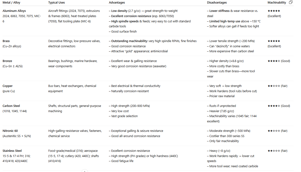
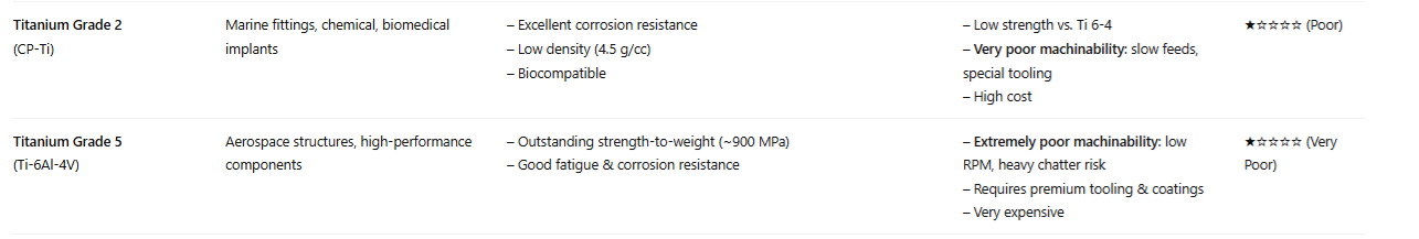
- Choose machinable alloys. Aluminum 6061, 7075, mild steels (e.g. 1018), and free-machining brass or stainless grades (303 SS) cut far faster and with less tool wear than exotic steels (17-4PH) or titanium.
- Internal corner fillets should have a radii above 1/32″, larger fillet is better, as larger end mills save time. Radii should be larger than the tool size, so do not pick a radius that is a standard tool size. when tool and corner radii match, the tool lacks clearance, forcing abrupt stops and pivots that reduce
efficiency and cause chatter. A tip is to use 1.3 times the radius of the closest tool size and aim for a radii-to-depth ratio of 1:4 for pocket radii. When cut depth exceeds twice the tool diameter, feed rates slow, increasing cycle time. - Generally speaking, floor fillets can be time consuming and difficult to machine and thus should be avoided unless vital to your part’s form and function.
- Holes Size. Size the hole for standard drill bits. Non standard will cause additional passes. Try to use this hole size across the part so tooling doesn’t need to be changed.
- Hole Depth. As the depth of a hole increases, so does the manufacturing difficulty. Excessively deep and narrow holes can lead to manufacturing issues such as tool breakage, drill walking, and chip evacuation issues. Hole diameter-to-depth ratio below 1:10. 1:4 is best.
- Design holes perpendicular to the surface, and create flats to ensure proper drill entry.
- Use thru holes over blind. Blind holes should have 25% additional depth to account for drill points and chip evacuation.
- Cavities greater than six times deep than they are wide are considered too deep; the ideal width-to-depth ratio is D < 4*W.
- Threads no more than twice the hole diameter
- Blind holes should have a unthreaded length of at least half the hole diameter.
- Wall thickness 0.030″ (0.762mm) metals and double for plastics.
- Specify tight tolerances 0.001 on critical fits only. All other feature 0.005-0.010″
- And obviously design the part so that it can be machined and all features are accessible.
How do you decide on material selection for a CNC-machined design?
- Balancing strength, weight, cost, and machinability is key.
- Only after modeling the cost impact of slower feeds and specialty tooling. I always check with purchasing/manufacturing for in-stock bar sizes to avoid custom sized material
How do you build in features that simplify fixturing and reduce setups?
Simplifying Fixturing: Machinist-friendly pads or faces on your part that mate directly against a vise jaw, tooling plate, or tombstone face.
Reduce Setup:
- Group all critical features on one primary face whenever possible—keep drilling, pocketing, and cutouts on the same side.
- Use 4- or 5-axis machining only when it truly reduces a second setup; otherwise favor 3-axis with smart datum placement.
- Document fixture-friendly features in your CAD model’s PMI: call out “Datum A face must contact vise jaw,” etc.
- Collaborate early with the workholding engineer—ask what standard tombstones, soft jaws, and step clamps they stock.
Explain your use of GD&T on CNC part drawings.
I always start with a clear datum scheme—primary, secondary, tertiary—anchored on the largest flat or boss. Position tolerances are applied to hole patterns that affect assembly. Apply geometric tolerances and tight dimensions on critical mating or functional features only, as this will increase inspection costs and part rejection for non critical features.
What strategies do you use to minimize cycle time on CNC parts?
- refer to DFM principles
How do you balance cost, lead time, and part performance in your designs?
I establish upfront what matters most—if cost is king, I’ll push for the simplest geometry and standard tooling; if performance is non-negotiable, I’ll accept specialty cutters or heat treatments, but I’ll model the cost delta in the BOM. For prototypes, I may sacrifice cycle time to iterate quickly; for production, I optimize for minimal setups and longest-lasting tools. I always track actual shop feedback on cost and lead time to refine my next design.
CNC Machining
Computer Numerical Control Machining. A subtractive manufacturing method, removal from a larger stock of material
3-Axis:
- X,Y,Z Motion.
- Can only work on the surface that is perpendicular to the part.
- Each reorientation creates more time on setup. This can cause problems like having to create custom fixtures for each orientation to keep the part secure, and introduce error in the next setup. It depends on the part geometry and how many setups are required to see if further axes are needed.
- Well suited for drilling, threading holes, cutting key slots
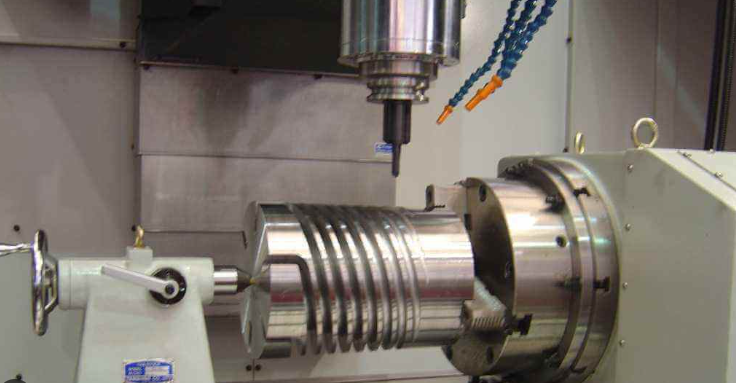
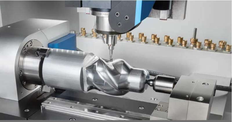
4-Axis:
- Has the typical X-Y-Z movement but with an added axis for rotation.
2 Types:
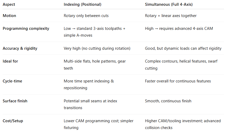
Indexing: 3+1-axis cutting: With the 4th axis held fixed, the mill executes a standard 3-axis toolpath (X, Y, Z) at that orientation.
Simultaneous: Continuous 4-axis motion: The rotary axis moves at the same time as X, Y, and/or Z. Enables the cutter to sweep complex, curved surfaces—guiding the tool tip along truly 4-dimensional paths.
4th axis machining is often used when cut-outs and holes are on the side of a part or made on a cylinder. By using 4-axis instead of 3-axis, you typically save more time because you’re eliminating the need for additional setups. It’s also easier to hold tight tolerances on all 4 sides of a part since it stays in a single setup.
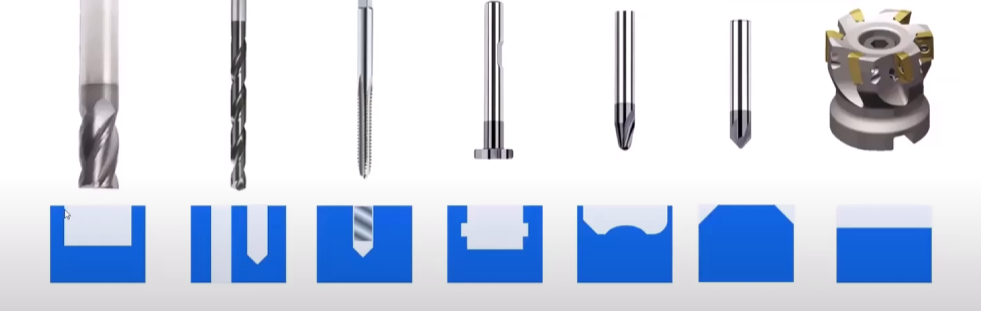
End Mill: Used for machining pockets
Twist drill: Through or blind holes
Tap: Threaded holes
Key-Seat cutter: For undercuts
Ball Nose: Used for surfaces for a smooth feature
Edge break chamfer tool: Used to break edges
Face mill: to take a lot of material off
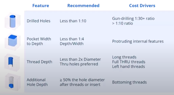
Cost-Driving Features
Its not about designing what can be made. Almost anything can be made. Its about cost.
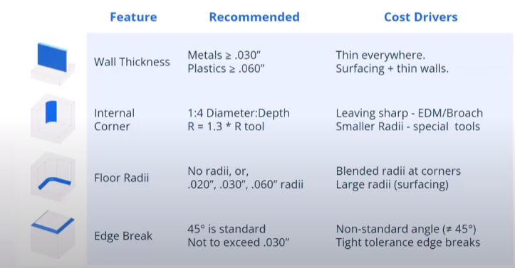
Wall Thickness: This drives cost up because you have to slow the spindle way down.
Leaving Sharp Corners: Cutting tools are round *****
Floor radii: Leave it, because you can cut flat on a floor in a pocket. Keep it standard because standard end mill tools have standard radii.
Edge breaks: do not modemost cases, as then if you dont model a 45 degree angle you are creating a feature which drives machine time. Don’t tolerance it too tightly cause you don’t want part rejected because of a thousandth off.
Drilled Holes: 1:10 diameter to depth ratio. Anything beyond this you will need a custom tool, which requires additional time.
Pocket Width to Depth: If you have a small pocket or cut feature, the machinist may not do any tool change and this decreases the diameter of the tool, increasing time to remove material.
Thread depth: you don’t need to fully thread a hole. Only a few threads are typically needed. Make sure to leave room in the hole for the tap to go past for full thread cutting.
Tolerances: Adding tolerances increases costs! Inspection is time. Special features GD&T symbols like cylindricity, profile may require even more money to inspect with a machine.
Material Selection
- Stainless steel machines at half rate of carbon steel
- Aluminum machines 4x faster than carbon steel
- Plastics even faster
Common Materials
- Aluminum 6061, Stainless steel 304, C360 brass, Delrin, Polyethylene