FEA

What is FEA?

  • Breaks complex geometries into bite side finite elements to do calculations
  • Curved path is approximated by straight segments 

This section shows all of the FEA workshops I have completed so I can better understand how to use the software and analyze the results.

Spring

k1 = F/u = 5/0.0234 = 213.7 N/m

k2 = 5/0.0000615 = 8130.1 N/m

Bracket

Heat Sink Thermal Analysis

Experimenting with different convection coefficients

Bracket FEA #2

Experimenting with removing material that is unnecessary for strength. 

Venturi Tube

Charcoal BBQ

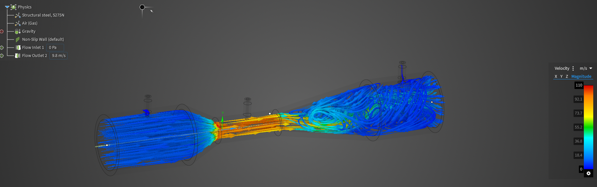
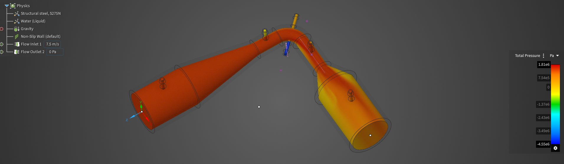
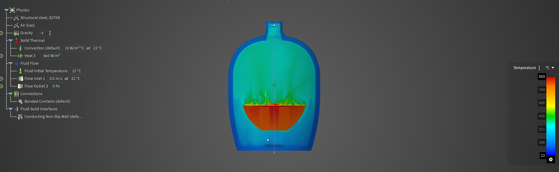
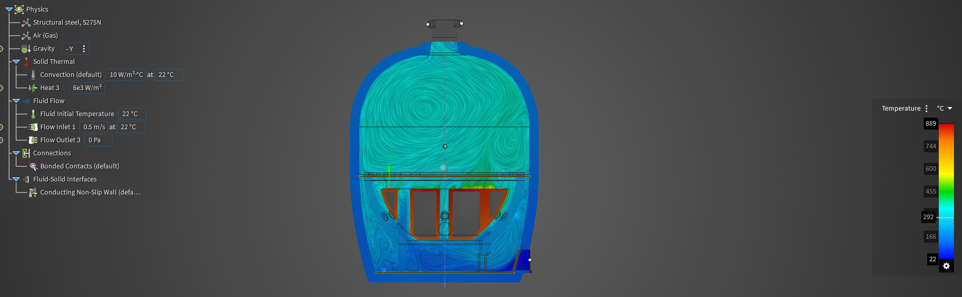
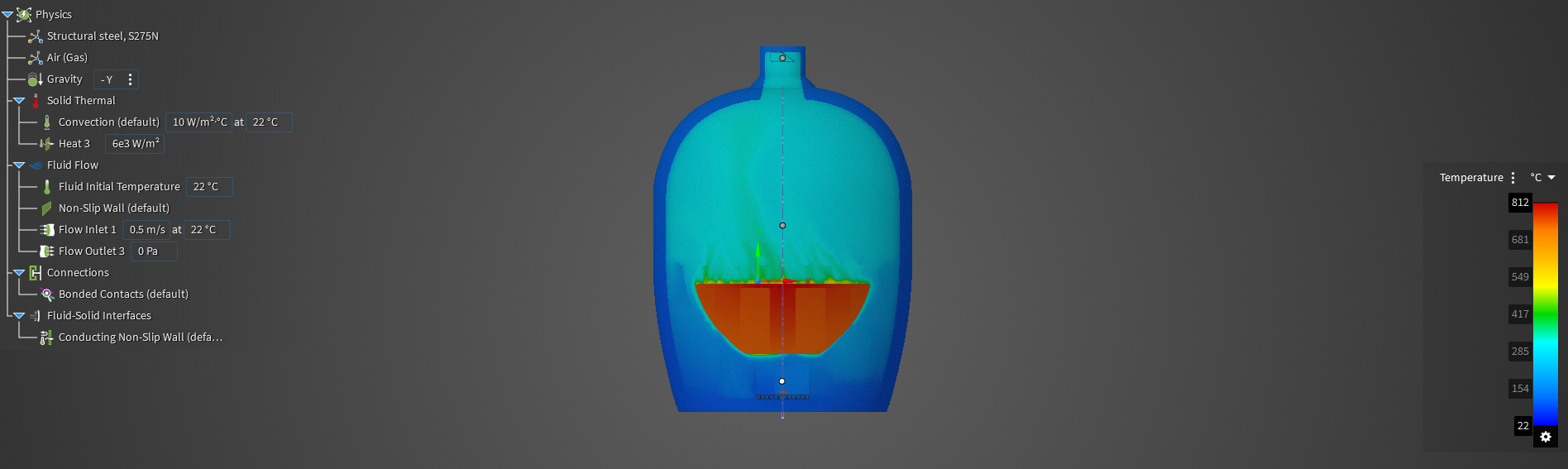
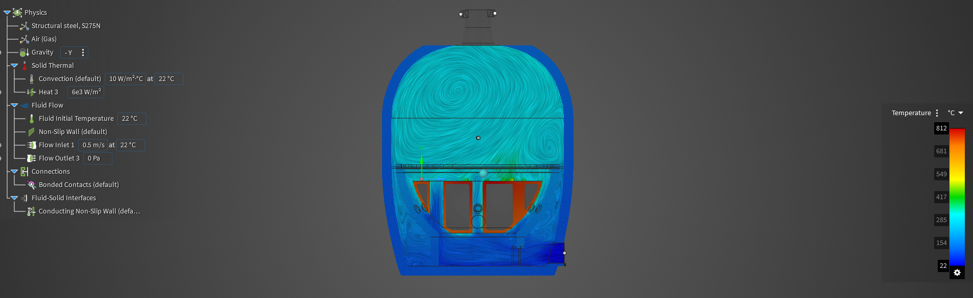
Couples a fluid dynamic simulation with a thermal simulation. We want to see what effect the airflow has on the temperature of the solid part of the grill. The bbq allows for good convection of heat and good distribution of airflow to allow the food to cook uniformly. Here is the real world data gathered from my instructor. Thermocouples and hotwires in various conditions to understand what boundary conditions we should be using for inlet. Ambient temperature and pressure going in, on the way out the velocity is a little higher. 

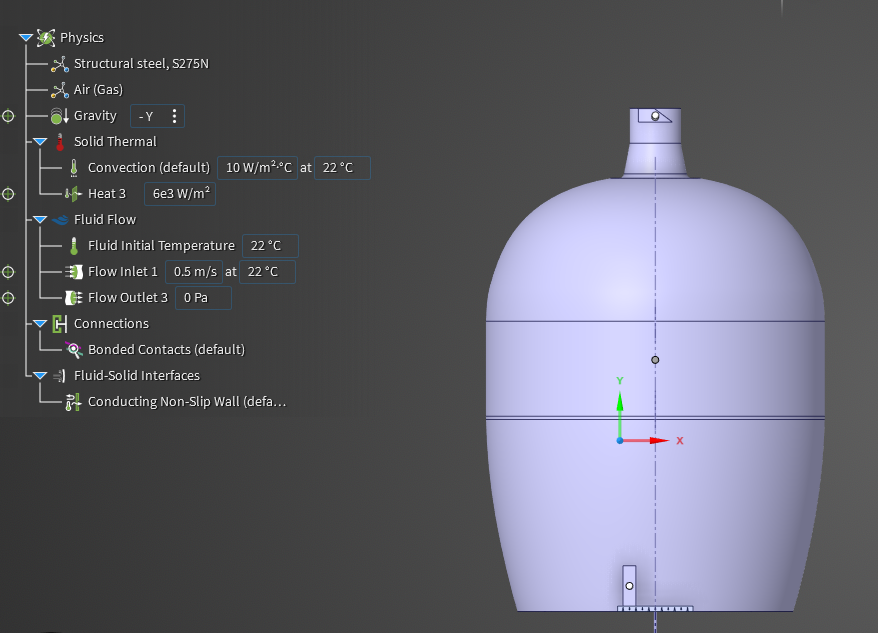
The bowl where all the charcoal is, we are simulating it with a heat source. A certain amount of w/m^2. Very difficult to simulate the combustion process, but is doable with enough time. Assuming the heat source is a static element. 

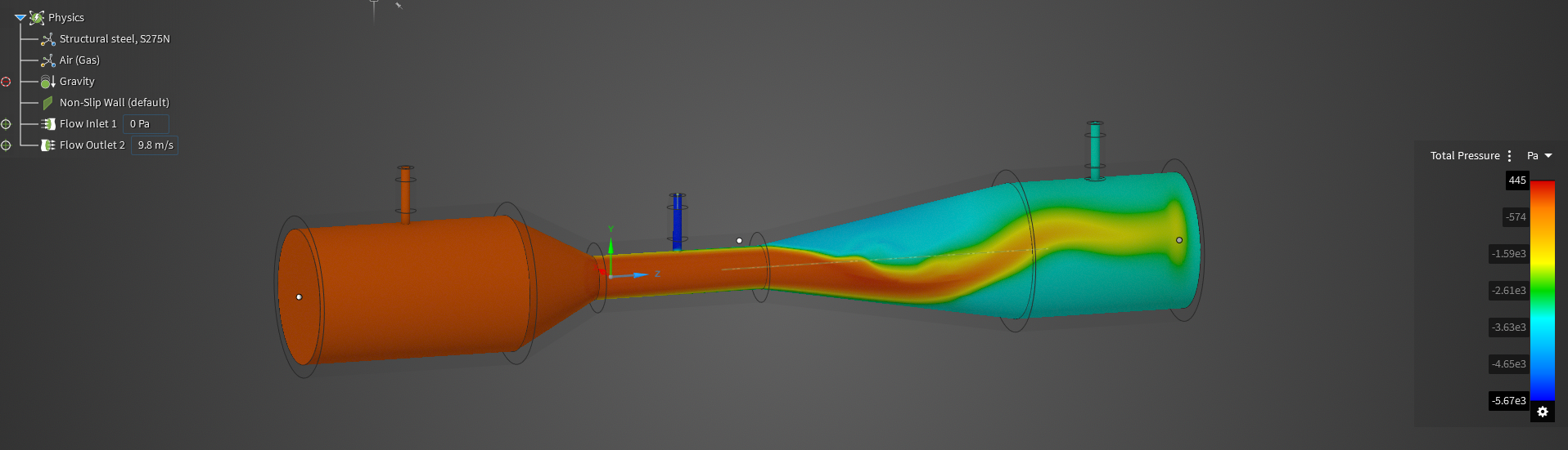
Inlet and outlet are allowed to change by user input. A larger inlet allows more air to feed the combustion process. If you have a smaller outlet, it is going to generate pressure and heat. 

Trying to simulate so we can not just guess how to cook food. 

  1. Gravity is added to this simulation. Because as you heat air, that changes the buoyancy and that’s why hot air rises. That effect is something we want to capture here. 
  2. Inlet: The air velocity measures is roughly 0.5m/s. The initial air temperature is ambient air, measured at 22 degrees Celsius. 
  3. Outlet: Exhausting to the atmosphere, therefore 0 Pa. 
  4. Heat Source: Set to 6000W/m^2. Added up the area where the charcoal sits and it is 1 m^2. Measured it to be 6000W ~ 300 degrees celsius.  
  5. Convection: How much convection is happening? As air  is touching the rest of the surface, we are losing heat. We are losing heat at 10W/m^2 C. 
  6. Fluid Solid Interface: It is a non-slip wall, it has no velocity at the wall, but is a conducting surface, meaning that heat can transfer. 

Extracting results #1 (small inlet):

  1. Charcoal bowl measures 800 degrees celsius as expected because this is the heat generating object. 
  2. Outer surface is much lower at 150 degrees C, because convection is occurring. Exterior faces are touching air that is 22 degrees. 
  3. The geometry of the inlet allows a small amount of air in. This is why it is quite hot at the inlet. 
  4. Air coming in at inlet is 22 degrees, and immediately starts mixing and heating up because the air around it is getting swirled up due to the buoyancy effect. 

When we open the inlet, the cooking area temperature has dropped from 400 degrees to 320 degrees. Bringing more cold air in decreases the temperature because we haven’t told the simulation that the fire will burn hotter with more air. This tells us that the 6000W/m^2 isn’t the correct answer anymore. This is a simulation where we are inputting parameters as an indirect approach to match the data we collected. We don’t know how much the fire is heating in W/m^2, we only can see the inlet and outlet information from real world data. When we double the heat to 12000, the temperature increases to ~500 degrees. 

Connecting Rod Between Piston and Crankshaft

Ignoring the fact that there are fasteners. This is a simplified analysis to optimize the I-Beam member for a tensile load case. Assuming that the 2 pieces are bonded together in this case.  

As the piston comes to the top, and reverse direction, all of that inertial force is trying to “tear away” the connecting rod from the crank shaft in tension. 

We can see a small deformation of 0.003 mm which is what we can expect for this moderate loading. 

Can see a large concentration of stress at this point. Could be a possible point of interest when reevaluating the design. 

MRI BED BOLT FEA

Capstone Link FEA

Transient Structural Simulation of Spinning Crankshaft

Background Information: We start to become concerned when the piston begins to compress the mixture, because the forces and pressures are going up. When we ignite the mixture and combustion happens, the internal pressure starts to decay. We are going to simulate the compression and power stroke.