Technical Approach and Design:
Step 1: Identified the main constraints of the mechanism.
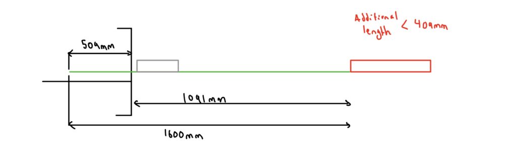
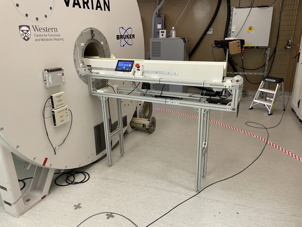
- A length of 1.5m that does not impede people from walking around the MRI scanner
- Mechanism should be as simple as possible, to minimize complexity of machining, and purchasing specialized components
- Initial constraint that the bed should be on a removeable cart and easily removeable from the scanner
- Predefined tray length and size that the marmoset lats on. 1.6m in length.
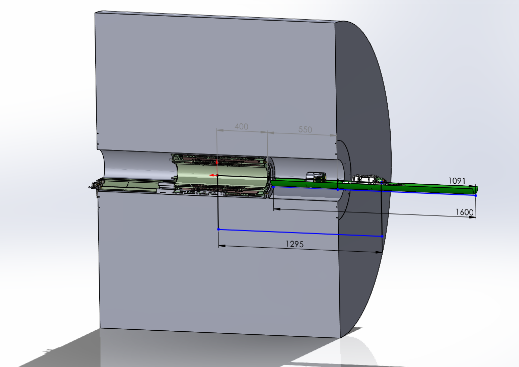
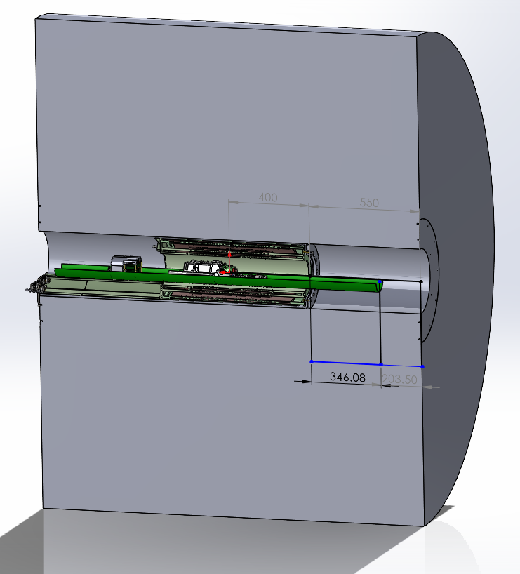
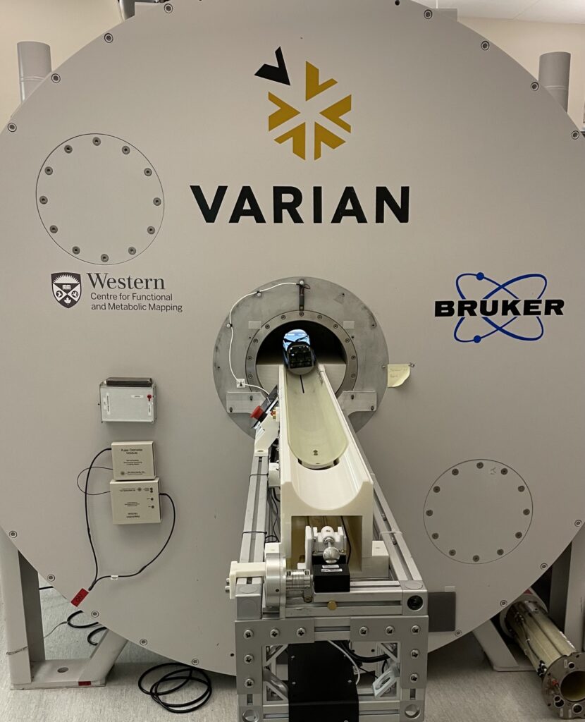
- Predefined coil diameter, and distance to isocenter. (950mm)
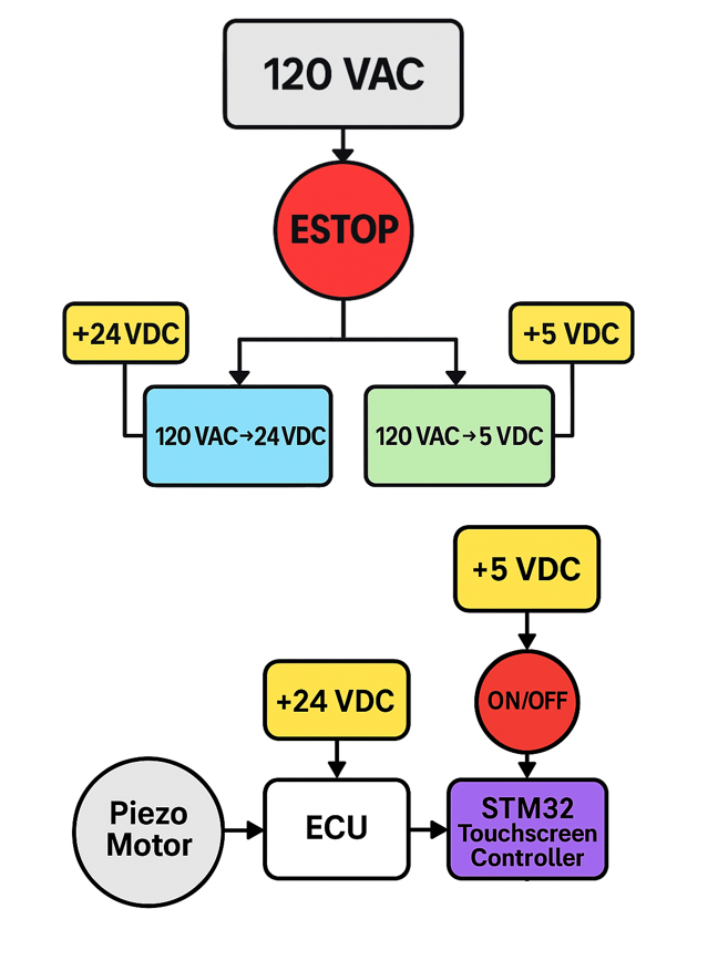
- Every part must be non-magnetic. Plastic, aluminum, brass, 316 stainless steel allowed outside the bore.
Step 2: Conceptually decide what the general mechanism was going to be. I sketched out multiple concepts to brainstorm ideas, from using research information to gather ideas, and look at existing MRI beds in the facility to create my own ideas.
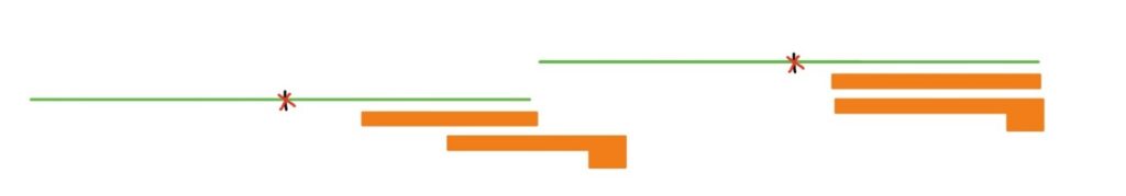
Having the tray fully outside the bore makes the bed greater than 1.6m. 2 Options developed:
Option#1
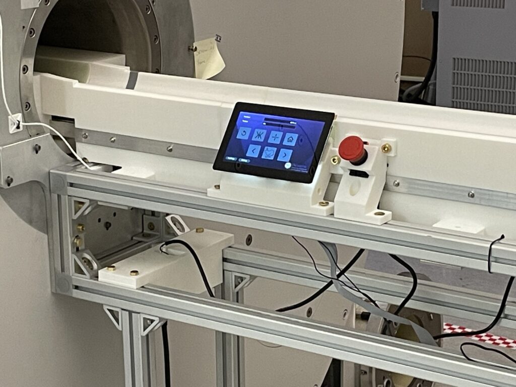
Mechanical Design
Frame and Drive Mechanism
- Originally Designed a removeable cart on wheels
- Needs of supervisor changed, and he now wanted a permanently installed version with no supports (cantilevered beam)
- With the frame already designed for the cart application, the weight of the modified version for the cantilevered beam was already determined.
Step 1: Simplified the Geometry for a static analysis
Step 2: Added the appropriate contacts/connections.
Step 3: Create the correct mesh
Step 4: Define the analysis settings.
Step 5: Material Properties
Step 6: Add the loads and fixed supports
Step 7: Analyzing the result files
The goal here is to determine when bolt failure will occur and if the 4 M6 bolts will be sufficient for mounting without supports.
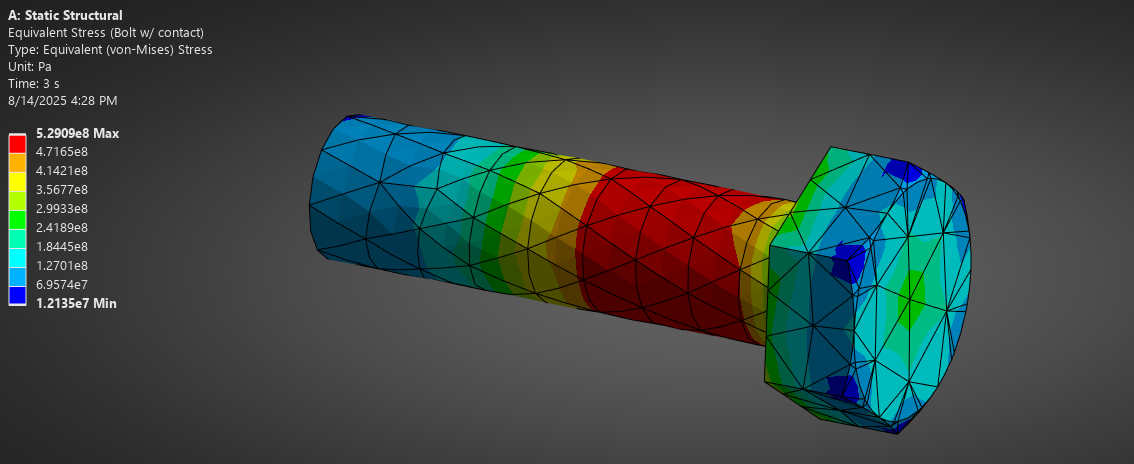
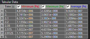
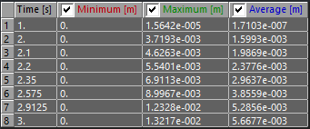
Equivalent Von Misses Stress in the highest stressed bolt
Tensile Yield Strength of the bolt is 450 MPA. We can see from the table that around 2.35 seconds the stress is 460 MPA. Therefore, at 2.3 seconds the load is 1900N (3000N/s x 0.3s = 900N). This indicates that if someone were to sit on the end of the frame, they would need to weigh 194 kg (427 pounds).
This is a large amount of weight, and it does give a large enough safety margin.
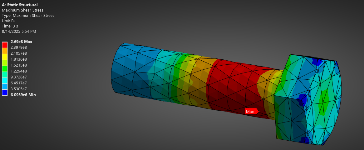
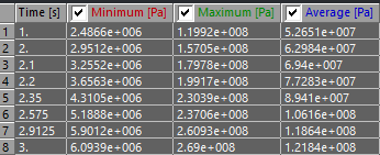
Maximum Shear Stress in bolt
Why is shear stress present after preload?
In ANSYS, Maximum Shear (Tresca) is a scalar derived from the principal stresses:
τmax=σ1−σ3/2
In simple uniaxial tension from a bolt preload, σ1=σaxial, σ1=σaxial, σ3 = 0.
τmax=σ1/2
At 2.3 seconds (1900 N) the maximum shear stress is 230 MPA. For this material, the shear yield is 260 MPa. THis would mean that the bolt would not fail, but as before the von misses combined bending, axial, and shear to identify yielding at 2.35 seconds.
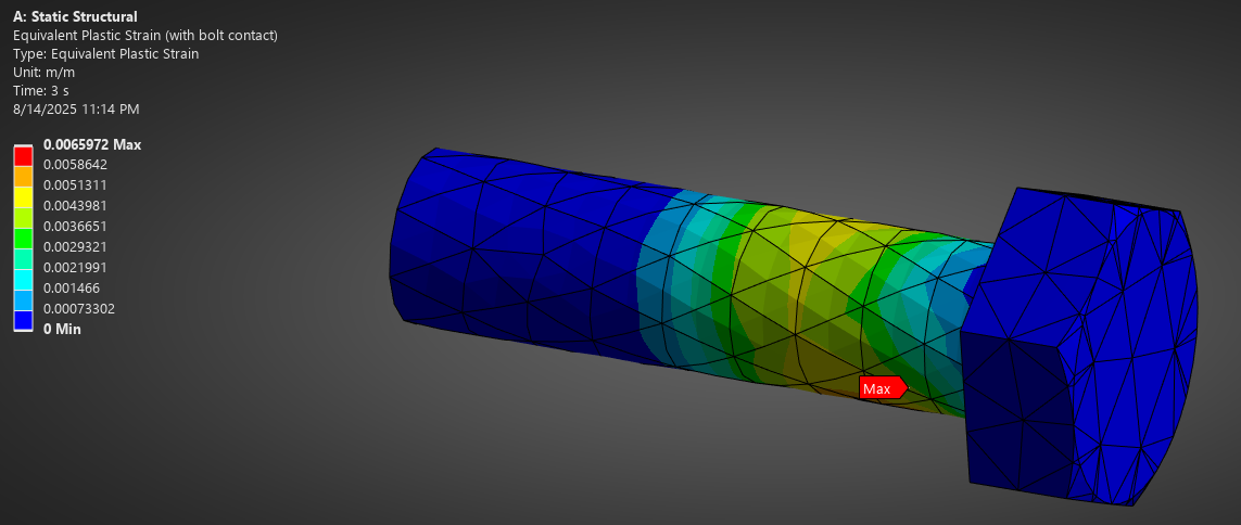
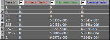
Equivalent Plastic Strain
We can actually look more in depth to see that plastic strain begins between 2.1 and 2.2 seconds, which will correspond to an external force of 1450 N. N(t) = 1000 + 3000(2.15 – 2).
This now equates to 147 Kg (324 lbs).
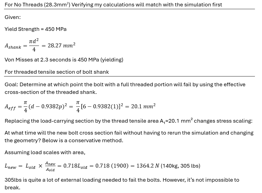
But we have to remember something. The modeled bolt is 6mm in diameter, and does not factor in the threads that create a thread tensile area of 20.1mm^2 instead of 28.3mm^2 cross section.
Lets do some calculations:
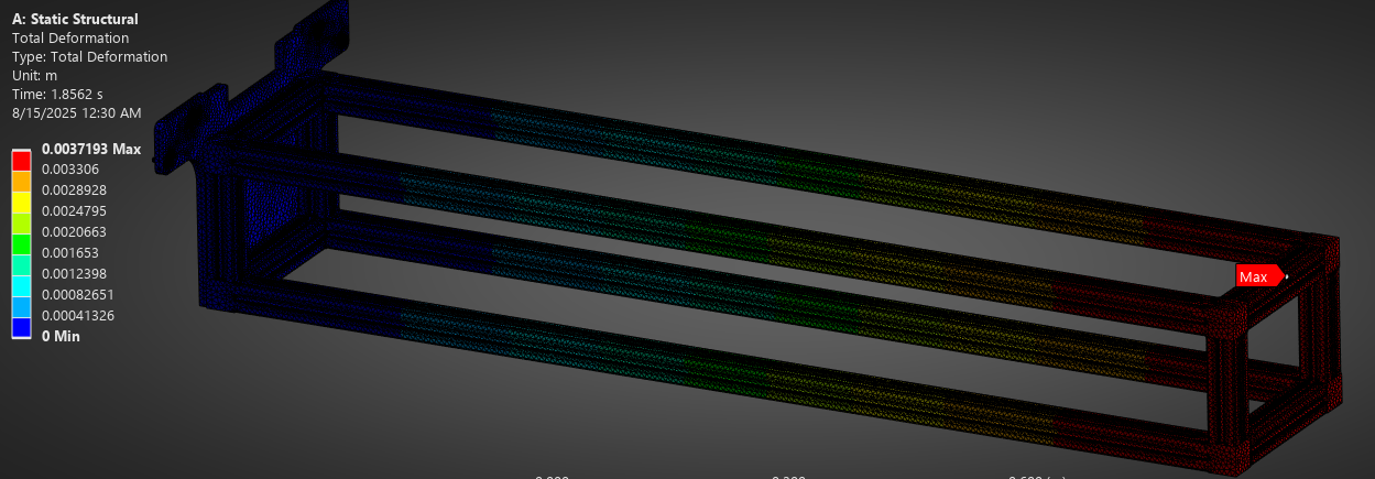
We can see that with just gravity applied (Start of step 2) the end of the frame sags by 3.7mm. This is enough to cause misalignment in mechanical system and may cause problems that could have been avoided. Any small external load adds even more deformation.
In conclusion, it was decided that supporting legs at the end of the frame was the safe decision. The possibility of bolt yielding, and the sagging of the frame were something we didn’t want to try out and see what happens.
Also the effect of pushing on the frame and releasing is not known. It may cause the frame oscillate, further affecting the mechanism alignment and structural integrity.
Also, 316 stainless steel is very slightly magnetic. The magnetic field may loosen the bolts over time which is a big concern. If we selected brass bolts instead, these would fail almost instantly with a yield strength of only 265 MPa.
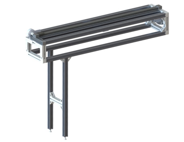
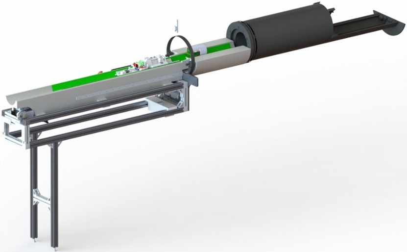
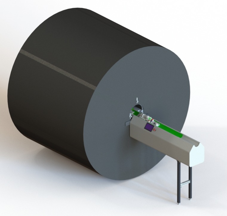
New Frame Design
Added support legs to the rear to eliminate the potential failure and deformation errors as discussed during FEA analysis.
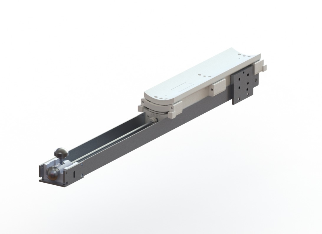
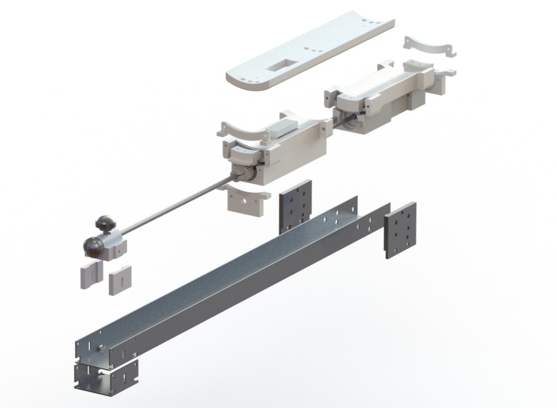
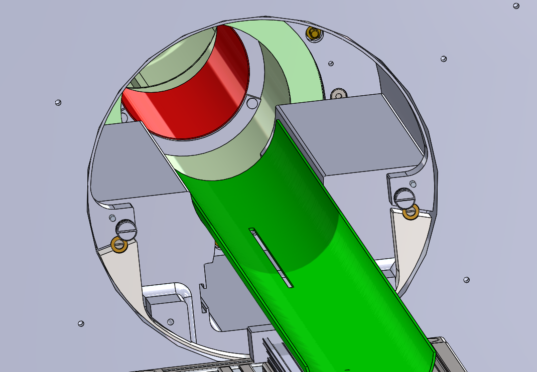
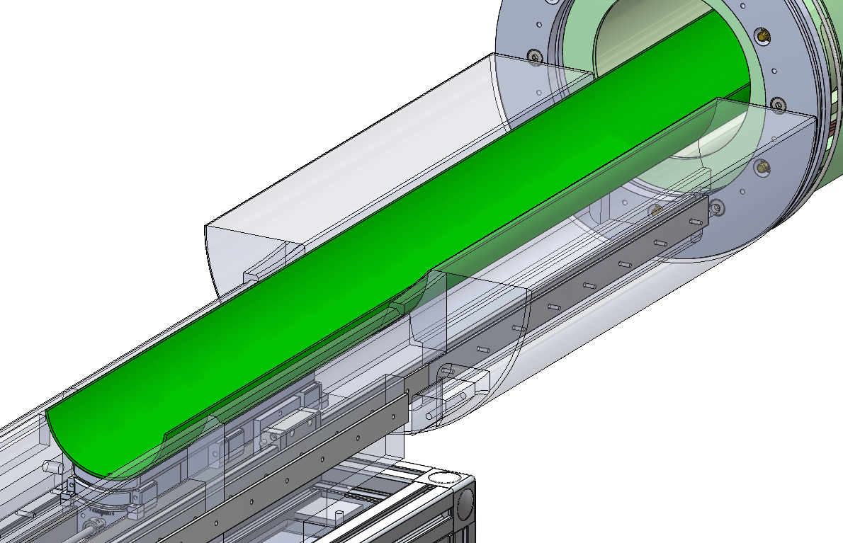
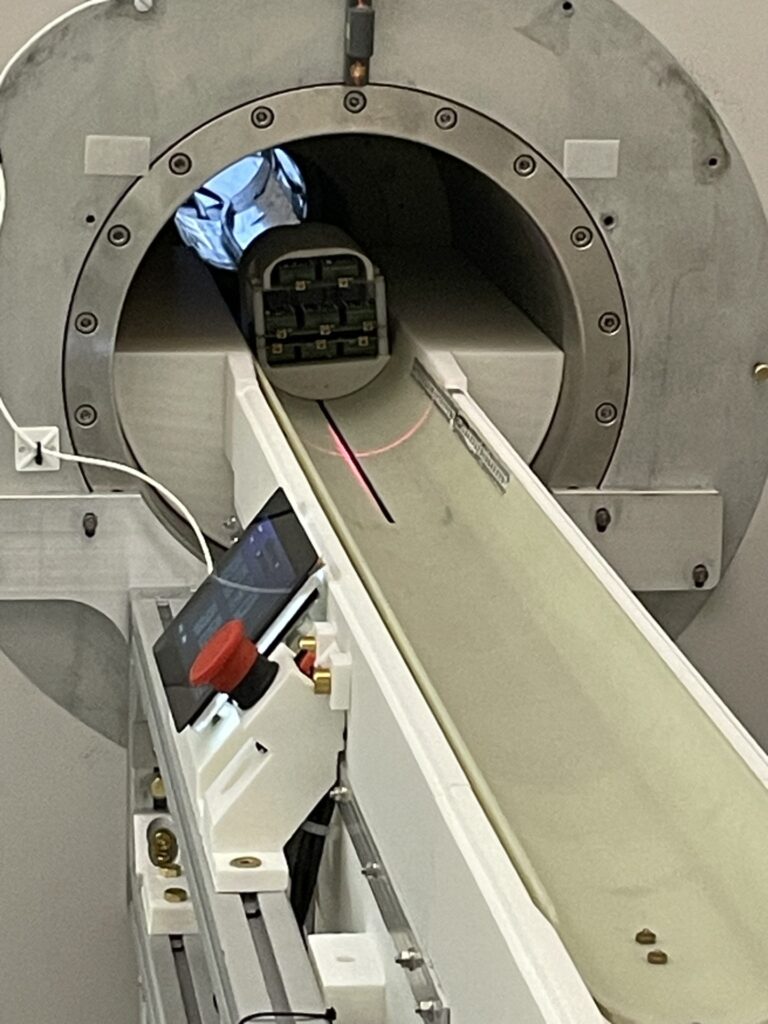
Originally had the tray just be guided by the 3D printed bore guide due to the restriction of no permanent installation of parts in the bore.
However, this changed because this was now a permanent install instead of the removable cart design.
To ensure a full linear actuation, two linear guide rails were installed into the bore guide. It also ensured no sagging of the cantilevered beam.