MRI Bed Project
FEA
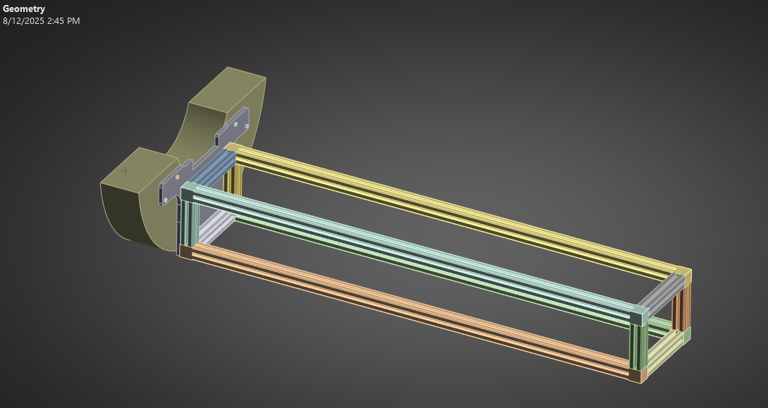
Step 1: Simplified the Geometry for a static analysis
Step 2: Added the appropriate contacts/connections.
Bolt Joint Connection
The bolt head to plate = frictional contact. Made an imprint to face of plate where bolt head applies pressure using ansys spaceclaim. Augmented Lagrange was selected for formulation. It is best for frictional contacts. Small Sliding = off.
Finite (large sliding is turned on because:
Recomputes the closest-point projection every iteration; a contact node is free to “walk” across multiple target elements.
Updates the contact normal and tangential directions as the bodies rotate/tilt.
Allows open–close and re-contact anywhere within the pinball region.
Costs a bit more, but it’s the physically correct choice for noticeable slip, edge contact, rocking, or separation.
- Step 2 and 3 adds an external load designed to partially unload and separate the plate from the magnet. That moves the contact patch toward an edge (rocking) and can produce re-contact at a different location.
Rule of thumb
Slip distance ≪ 10% of the contact length scale (e.g., < 0.1× head diameter),
Relative rotation is just a few degrees, and
No separation/re-contact will occur.
Bolt thread to scanner hole = bonded. This is because the bolt shank fails before threads do in most scenarios. The shank is exposed to bending or shear whereas the thread portion is backed up by the “nut” material, which prevents bending. The break is just ahead of the first engaged thread in the nut, at the shank-to-thread transition. That’s where you get a combination of stress concentration and highest applied moment.
Plate clearance hole to bolt shank = frictionless, Augmented Lagrange, Pinball Radius = 0.4mm. This contact will introduce shear into the bolt shank once the bolt joint begins to seperate. As the clearance hole in the plate comes in contact with the bolt, shear will be added.
Why a Pinball Radius of 0.4mm?
When running the initial contact tool, I saw the original programmed control radius to be 1.7mm. This will cause the bolt to see a very large neighborhood, so nodes can flip into a near contact state long before the hole actually reaches the bolt. This will create artificial pressures/penetrations early. Setting the pinball ~ radial clearance (0.25) + ~one local element edge (0.1) keeps the pair open until the gap truly closes. When rerunning the contact tool, the initial status of this contact is OPEN. This is what I want to see.
Plate to scanner (step 1) = No separation during preloading. Ensures gravity force does not affect movement of plate. (I was having this error in the beginning)
Plate to scanner (Step 2 and 3) = Frictional Contact with augmented lagrange, small sliding off for the same reasons. Pinball region is manually inputted to 6mm.
Why a pinball region of 6mm? ***************************REDO
- In ANSYS contact, each contact node searches for nearby target faces inside a sphere—the pinball.
- If a target face is inside the sphere, that pair can become active contact; if not, the node is FAR.
With finite (large) sliding, this search is repeated every equilibrium iteration, so the radius controls how far a node is allowed to migrate to a new target as the bodies separate/slide/rock
- pinball ≥ (initial gap + expected normal separation + a small safety margin).
- plate and magnet start touching (gap ≈ 0), and even in my “separation” step the measured openings are on the order of 10⁻⁴–10⁻³ m. So a 6 mm pinball is orders of magnitude larger than the actual opening—plenty to keep the contact “in range.”
- 6mm is a good choice because:
If you leave the pinball Program Controlled, ANSYS often picks a generous value (frequently ≥ one element size or more). That can cause:
Spurious “jump” contact: when the plate peels, nodes may reattach to the back face of the magnet or to a neighboring feature that sits within a big pinball.
Chatter/overconstraint: multiple candidate faces inside the sphere → frequent switching → convergence trouble and ghost pressures.
Artificial stiffening: early contact with non-mating surfaces makes the joint look stronger than it is.
- Setting pinball = 6 mm (< 7.5 mm mesh element) narrows the neighborhood to “what we physically expect”. 6 mm pinball is intentionally a bit smaller than the 7.5 mm mesh size to exclude nearby, non-mating faces while still being much larger than any real separation you apply. ******************** REDO
Plate to frame = bonded. Tim contact = on, Trim tolerance of 5.5mm. Formulation = Pure Penalty. Pinball region = 6mm.
Why Formulation is Pure Penalty?
A “bonded” contact in Mechanical can be enforced three main ways:
a) MPC (multi-point constraints).
What it does: writes hard kinematic constraints (equal displacements) between coincident DOFs.
Pros: exact tie (no relative slip/gap), very stiff; minimal penetration by construction.
Cons: can create constraint loops (overconstraint) when many small faces meet one large face, or when the tied region winds around corners/holes; sensitive to topology mismatch; poorer robustness with large deformation and nonmatching meshes; can artificially over-stiffen the model.
b) Augmented Lagrange (AL).
What it does: adds Lagrange multipliers with a penalty “assist”. It iteratively adjusts the contact traction so the kinematic error goes to (near) zero.
Pros: accurate enforcement; sometimes more accurate pressure recovery than pure penalty.
Cons: more nonlinear iterations; if the tied patch is big and the meshes are dissimilar, AL can still be touchy; more tuning (stiffness factors, augmentation).
c) Pure Penalty (what I am using).
What it does: replaces the “bond” with very-stiff linear springs (normal & tangential) between the two surfaces. The solver tries to drive relative motion to ≈0 by using a large contact stiffness kn, kt, computed from local E, area, and element size.
Pros: very robust with many-to-one ties, dissimilar meshes, big areas, and large deformation; avoids MPC loops; converges faster; easy to run.
Cons: it permits microscopic relative slip/gap, so the bond is “numerically compliant.” If you set stiffness too low you’ll see visible slip/penetration; too high and you re-introduce ill-conditioning.
- Why it is a good choice: bonding many smaller frame faces to one split line on the plate (many-to-one). Penalty avoids the overconstraint/MPC loop issues and is typically the most robust & stable way to glue non-matching meshes.
Why Trim Contact = ON and Trim Tolerance = 5.5mm?
What “Trim Contact” does
When you define a bonded region by selecting faces, Mechanical builds an interaction patch by projecting contact nodes onto the target. Raw projection can (a) spill past edges, (b) include slivers around holes/chamfers, or (c) miss slightly misaligned areas because of tiny CAD/mesh gaps. Trim Contact = On tells Mechanical to clip the active bonded patch to the true overlap of the two surfaces (their intersection in projection) within a user tolerance. That prevents:
Bonding across nearby but not intended faces, and
Losing parts of the bond because of small initial offsets.
What the Trim Tolerance is
It’s a geometric allowance for the projection/intersection, not a stiffness.
A node on the contact face is considered part of the bonded intersection if its projected distance to the target is ≤ the Trim Tolerance.
So it covers minor mismatches, mesh stair-stepping, or slight CAD gaps while avoiding bonding faces that are truly separate.
Why 5.5 mm in mymodel
local element length at that interface is ~7.5 mm. With coarse, non-conformal meshes and flat-on-flat geometry, a few millimeters of trim tolerance keeps the bond continuous despite stair-stepped edges or tiny offsets.
I chose 5.5 mm as a conservative but sub-pinball value: it is smaller than your nearby contact pinball (6 mm radius) and smaller than the typical hole/feature spacing, which helps avoid accidentally bridging to unintended faces while still capturing the intended overlap everywhere.
- Validated: turned on Contact Tool → Status and confirmed no “Over Constrained” regions appear and that the bond visually matches the intended footprint.
All other parts bonded. I learned that you cannot have multiple contacts with the same face involved. It causes an augmented lagrange error.
Step 3: Create the correct mesh
1. I made mesh element size to 7.5mm. This was obtained from an Ansys tutorial.
2. Created a specific body mesh size for the bolts of 2.5mm. A small mesh is required here because the body is smaller and is an important aspect of the simulation.
3. Created a face mesh sizing of 2.5mm for all areas where the bolts are bonded to. That is the thread in the scanner, and head imprint on the plate. This is needed so that the meshes of both the body and contact surfaces are equal.
Step 4: Define the analysis settings.
Number of steps = 3.
Step 1: Preloading Step. No force acts on the system, so preload can take effect properly.
Step 2: An applied force of ramping from 0N to 1000N to apply just enough force to not seperate the bolt joint. Gravity also ramps from 0 – 9.81m/s^2.
Step 3: An applied force of ramping from 1000N to 4000N to see the effects of separating the joint. Gravity is also in effect here.
Solver Type = Direct. A direct solver is defined because it is the recommended type for frictional contact, bolt pretension, large deflection, and lots of contact pairs.
Large Deflection = On. The large load ramping it is expected to cause large deflection.
Only Stress, Strain and Contact Data are selected outputs (All I need) and this reduces sim time.
Turning Generate Restart Points = Off is safe for accuracy—the physics and final results don’t change. It only affects recoverability and workflow. Saves time.
Step 1 Specific Settings:
- Store Result At: Last time point. This tells Mechanical to only write results for the final converged point (the very end of the solve) to the .RST file. I don’t need intermediate steps for the preloading.
Step 5: Material Properties
Bolts: Created a new material of 316 Stainless Steel to add plasticity property, so I can see when the bolt begins to yield.
Step 6: Add the loads and fixed supports
Step 7: Analyzing the result files
The goal here is to determine when bolt failure will occur and if the 4 M6 bolts will be sufficient for mounting without supports.
Equivalent Von Misses Stress in the highest stressed bolt
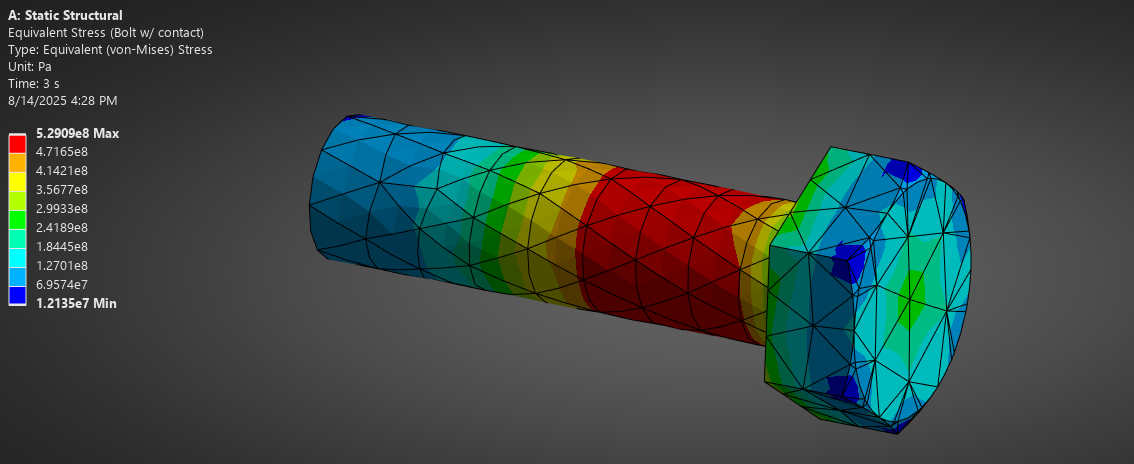
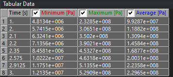
Tensile Yield Strength of the bolt is 450 MPA. We can see from the table that around 2.35 seconds the stress is 460 MPA. Therefore, at 2.3 seconds the load is 1900N (3000N/s x 0.3s = 900N). This indicates that if someone were to sit on the end of the frame, they would need to weigh 194 kg (427 pounds).
This is a large amount of weight, and it does give a large enough safety margin.
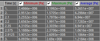
Maximum Shear Stress in bolt
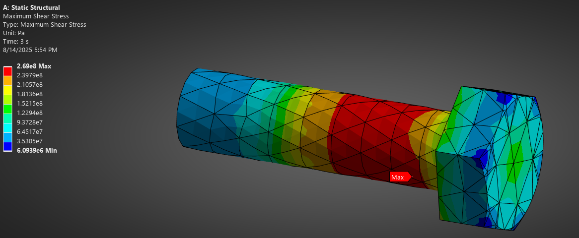
Why is shear stress present after preload?
In ANSYS, Maximum Shear (Tresca) is a scalar derived from the principal stresses:
τmax=σ1−σ3/2
In simple uniaxial tension from a bolt preload, σ1=σaxial, σ1=σaxial, σ3 = 0.
τmax=σ1/2
At 2.3 seconds (1900 N) the maximum shear stress is 230 MPA. For this material, the shear yield is 260 MPa. THis would mean that the bolt would not fail, but as before the von misses combined bending, axial, and shear to identify yielding at 2.35 seconds.
Equivalent Plastic Strain
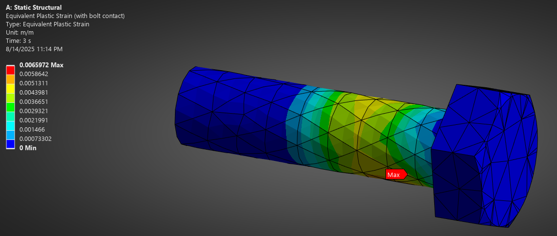
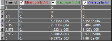
We can actually look more in depth to see that plastic strain begins between 2.1 and 2.2 seconds, which will correspond to an external force of 1450 N. N(t) = 1000 + 3000(2.15 – 2).
This now equates to 147 Kg (324 lbs).
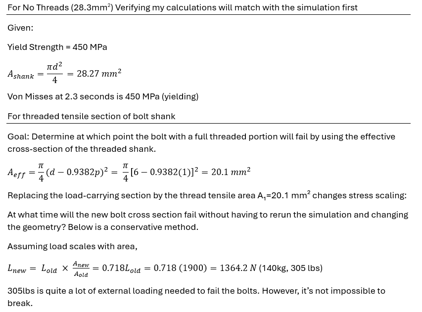
But we have to remember something. The modeled bolt is 6mm in diameter, and does not factor in the threads that create a thread tensile area of 20.1mm^2 instead of 28.3mm^2 cross section.
Lets do some calculations:
Deformation Results
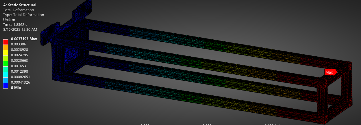
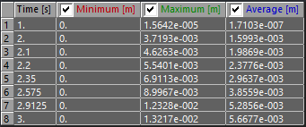
We can see that with just gravity applied (Start of step 2) the end of the frame sags by 3.7mm. This is enough to cause misalignment in mechanical system and may cause problems that could have been avoided. Any small external load adds even more deformation.
In conclusion, it was decided that supporting legs at the end of the frame was the safe decision. The possibility of bolt yielding, and the sagging of the frame were something we didn’t want to try out and see what happens.
Also the effect of pushing on the frame and releasing is not known. It may cause the frame oscillate, further affecting the mechanism alignment and structural integrity.
Also, 316 stainless steel is very slightly magnetic. The magnetic field may loosen the bolts over time which is a big concern. If we selected brass bolts instead, these would fail almost instantly with a yield strength of only 265 MPa.
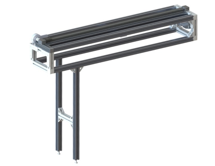
New Frame Design
Added support legs to the rear to eliminate the potential failure and deformation errors as discussed during FEA analysis.