
Branch #1
- Voltage divider scales voltage to properly turn on NMOS
- Zener diode clamps VGS to 6.2V to meet absolute maximum values
Branch #2
Overvoltage condition
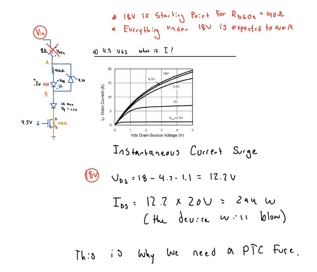
- PTC Fuse limits current as voltage increases. If no fuse, zener diode D9 will have too high of power dissipation
- Resistor sets the proper current through LED at 4.7V
- MOSFET is ON and VDS absorbs a large portion of voltage in branch
Undervoltage condition
- MOSFET allows current through the body diode, which would blow the Zener diode if the diode was not added.
Branch #3
Overvoltage condition
- PTC fuse limits current through zener diode to prevent it from blowing
- Zener diode clamps LED voltage to 4.7V for proper current.
Undervoltage condition
- PTC fuse limits current through zener
- Zener allows bypass of current to turn off LEDs.
How did I define the component values/parts?
1. (Branch 2) Need to select a MOSFET with a high VDS rating. I selected 100V NCE0103M NMOS.
2. (Branch 1) Need to define the turn on point of MOSFET which conducts during the first overvoltage condition but off during normal condition.
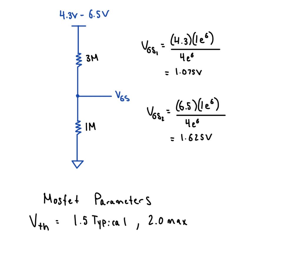
The MOSFET selected has Vth of 1.5V – 2V. Therefore, it will start to conduct at the overvoltage condition.
But how much current will it conduct at this state needs to be determined. After lab testing it was conducting around 1mA which is sufficient to see the LED ON.
3. (Branch 1) Added a Zener Diode of 6.2V to clamp VGS at high voltages so the first resistor drops the voltage
4. (Branch 2) Used R22, LED4, with a zener clamping at 4.7V for a point at which the voltage may be too high for the LED, causing too much current.
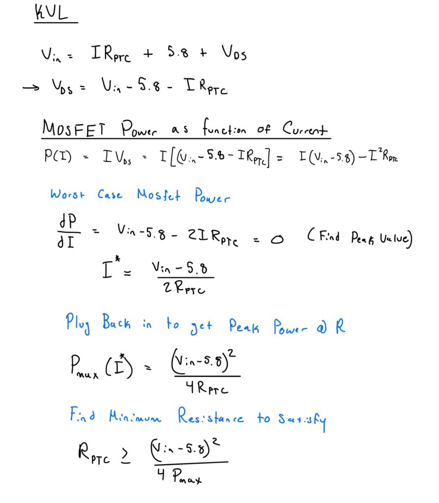
5. (Branch 2) Selected a PTC fuse with the correct tripping current.
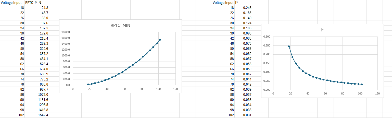
So I need to determine at each voltage what the resistance of the PTC should be based on voltage input.
How does a PTC fuse work?
Resistance is set by temperature. Temperature is set by self-heating I^2R vs how fast it can dump heat to ambient.
For any applied voltage/load, the part settles at a thermal equilibrium point on its I–V curve. At low current it sits near its cold resistance; as current (and power) rise it heats up, its resistance rises, and the operating point slides along the curve toward the high-R “tripped” region.
But ultimately I selected the PTC to act as a variable resistor which increases resistance as voltage increase.
To select the PTC fuse:
Max voltage drop ~ 100V
Max current allowance ~ 1A for both diodes due to power ratings
Need to first understand the circuit without the PTC fuse.
So now I need to find how to PTC fuse should limit current based on voltage input.
For a range of input voltages I found how the PTC fuse should react over time.
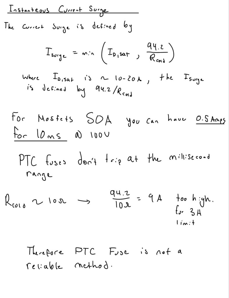
PTC fuse datasheets do not provide curves on the resistance as current increases.
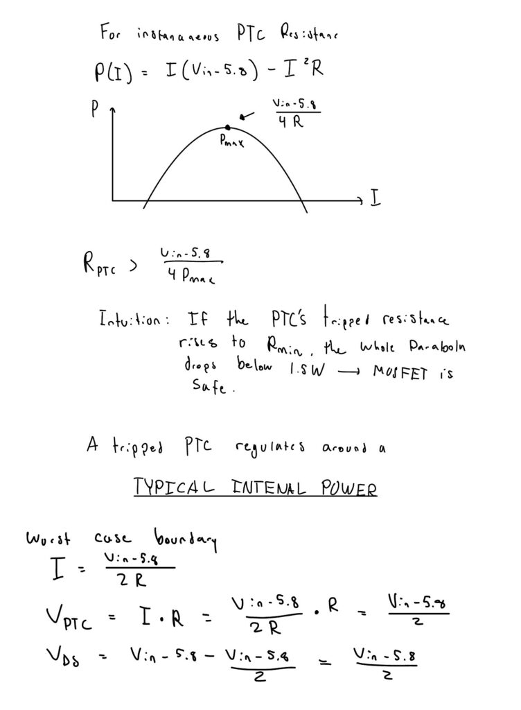
But we can use the “Typical Power” value.
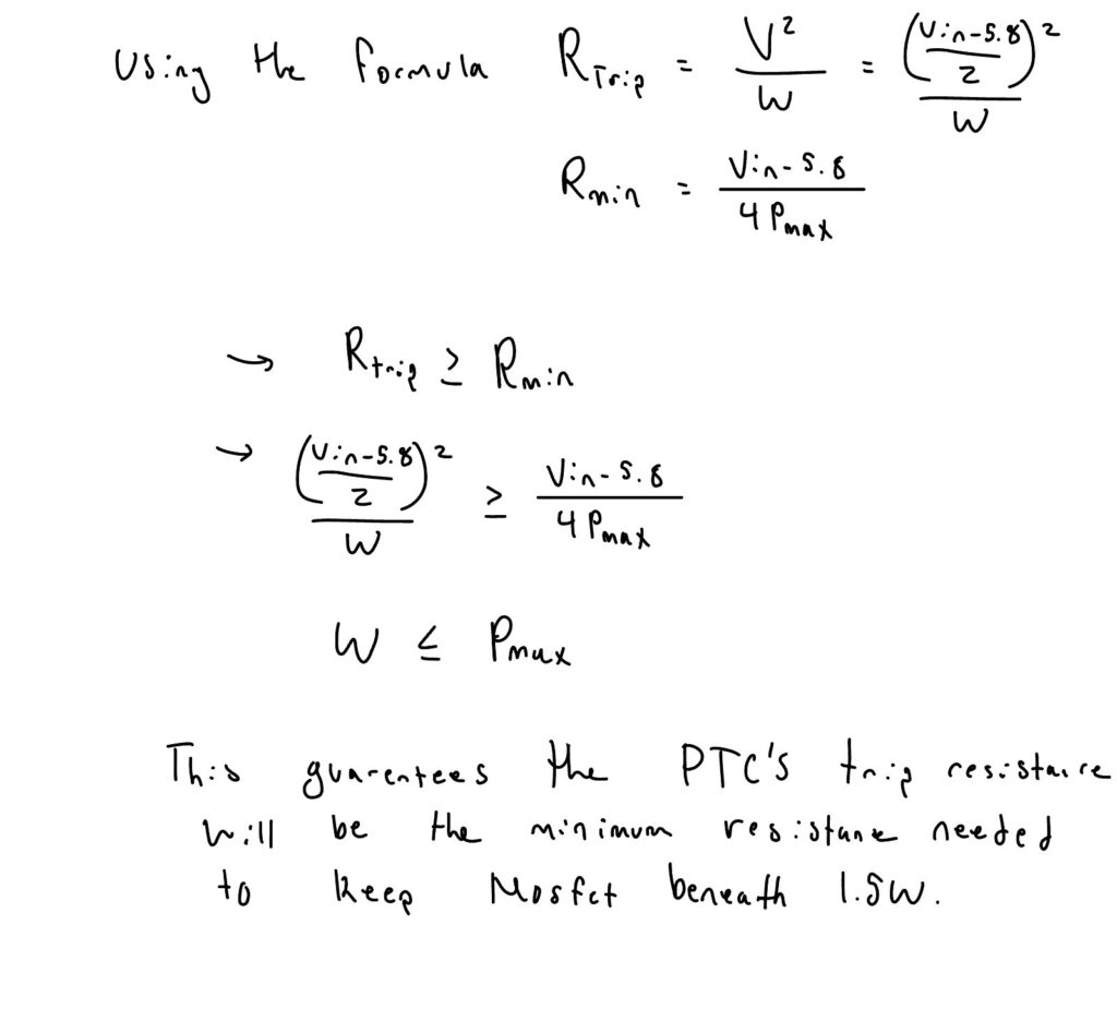
This is the power required to exactly match the heat lost by the tripped device to its ambient surroundings at 23C. By Ohm’s Law, power can be stated as: W = V²/R. R = V²/W.
Since the PTC acts to maintain a constant internal temperature, its apparent resistance will change based upon applied voltage and, to a lesser degree, ambient conditions.
Consider the following example….
A PTC with a Typical Power of 1 watt protecting a circuit using a 60V supply will demonstrate an apparent,
tripped resistance “R” of:
R = 60²/1 = 3,600 ohms
We can narrow the selection of the PTC down by:
1. Max voltage >> 100V
2. Typical Power < 1.5W
3. Itrip ~ 30 mA
4. Time to trip
Need a new method to sense voltage 7V-100V.